Sheet metal bending is one of the most common operations in sheet metal fabrication. It turns flat sheet into angled brackets, panels, chassis, covers, frames, clips, and enclosures by applying force along a bend line. Simple as it looks, bending has a major impact on cost, tolerance, fit, and appearance.
For engineers and buyers, the most important bending decisions are bend radius, material thickness, bend direction, hole placement, tolerances, and finish requirements. A design that respects these factors is easier to quote, easier to manufacture, and less likely to need rework.
What Is Sheet Metal Bending?
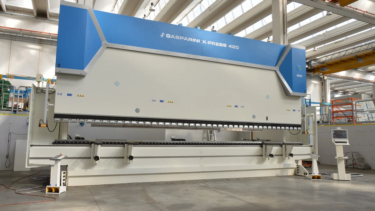
Sheet metal bending is a forming process that plastically deforms sheet material to a specific angle. The material is forced past its yield strength, so it keeps the new shape after the tooling is released. The process is often performed on a press brake, but it can also involve folding machines, roll bending, or dedicated forming dies.
Bending is different from cutting or machining because the material remains mostly intact. The challenge is predicting how the material stretches and recovers during the operation.
Common Sheet Metal Bending Methods
Source: Wikimedia Commons.
Several bending methods are used depending on accuracy, material, tooling, and production volume.
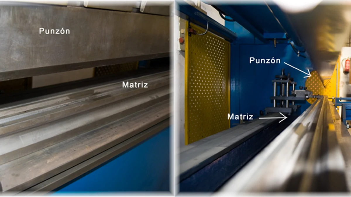
- Air bending: The punch presses the sheet into a V-die without fully bottoming out. It is flexible and widely used.
- Bottoming: The sheet is pressed more firmly into the die, improving angle control but requiring more force.
- Coining: High pressure forces the material into the tooling, producing high accuracy with greater tooling stress.
- Roll bending: Rollers form large radii or curved panels.
- Folding: A clamping beam holds the sheet while a folding blade forms the bend.
Why Bend Radius Matters
Bend radius is the inside radius of the bend. If the radius is too small for the material and thickness, the outside surface can crack. If the radius is larger than expected, the final part may not fit the assembly. A common starting point is to use an inside bend radius close to the material thickness, but the best value depends on material grade, temper, thickness, and tooling.
Stainless steel and harder materials generally need more generous bend radii than softer aluminum. Grain direction can also matter: bending across the grain is often more reliable than bending parallel to it.
K-Factor, Bend Allowance, and Flat Patterns
When sheet metal bends, the outside of the bend stretches and the inside compresses. Somewhere through the thickness is a neutral axis that changes length less dramatically. The K-factor estimates the neutral axis location and helps calculate bend allowance and flat pattern length.
Accurate flat patterns are critical because the blank must be cut correctly before bending. If the K-factor, bend radius, or tooling assumptions are wrong, the finished part may be too long, too short, or out of tolerance.
Springback and Tolerance Control
Springback happens when the material elastically recovers after the bending force is removed. The final angle opens slightly compared with the angle under the tooling. Harder materials, larger radii, and higher-strength alloys often show more springback.
Manufacturers compensate through tooling selection, over-bending, process experience, and inspection. For critical parts, it is useful to define which angles and dimensions matter most after bending rather than applying unnecessarily tight tolerances everywhere.
Design Tips for Sheet Metal Bending
Good bending design reduces production risk. Keep holes and slots away from bend lines unless distortion is acceptable. Use bend reliefs where flanges meet. Avoid very short flanges that tooling cannot grip. Keep bend directions and tool access in mind when a part has multiple bends.
If the bent part will be assembled with machined components, define datums and critical interfaces clearly. Sheet metal tolerances and CNC machining tolerances behave differently, so the drawing should separate cosmetic dimensions from functional ones.
For broader manufacturing planning, this article pairs well with CNCMAVEN’s overview of sheet metal fabrication and the guide to DFM considerations for CNC milling.
When to Use Sheet Metal Bending
Sheet metal bending is a good choice for brackets, covers, panels, guards, chassis, electronics housings, and lightweight structural parts. It is especially effective when a part can be made from laser-cut or punched flat stock and then bent into the final shape.
It may not be the best choice when the part needs thick 3D features, deep pockets, complex internal geometry, or extremely tight tolerance relationships across many surfaces. In those cases, CNC machining, casting, extrusion, or a hybrid assembly may be better.
Conclusion
Sheet metal bending is a cost-effective way to create strong, lightweight metal parts, but the design must account for bend radius, springback, tooling access, and feature placement. CNCMAVEN can help review your drawings and choose practical bending, machining, and finishing strategies before production starts.