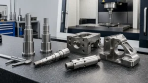
CNC milling is one of the most widely used manufacturing methods today. In this guide, we summarize common design considerations.
Key Takeaways for CNC Milling DFM
Key Takeaways for CNC Milling DFM
- Design around cutter and holder access, not only the visible cavity in the CAD model.
- Keep functionally related features in a common setup where practical, and define their datum relationship on the drawing.
- Treat deep pockets, thin walls, small deep holes, and long threads as review points rather than universal pass-or-fail rules.
- Mark critical fits, sealing faces, cosmetic areas, edge requirements, and post-finish dimensions explicitly.
- Send the model, controlled drawing, material, quantity, finish, and inspection scope together for a useful DFM review.
For project-specific manufacturing review, see CNCMAVEN’s custom CNC machining services.
Basic Principles of CNC Milling Design
The size of the tools used in milling is a crucial factor to consider when designing parts. It’s important to consider whether new features added during design can be machined with existing tools. Reducing the number of setups not only saves machining time but also improves accuracy. Minimizing material removal can save both time and costs.
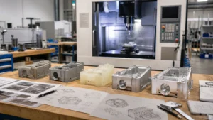
1. Minimize the Number of Setups
The machining path is a major design constraint in CNC milling. To reach all surfaces of the model, the workpiece must be rotated/flipped multiple times. Each time the workpiece rotates, the machine base must be recalibrated and a new coordinate system defined.
Consider the number of setups for two reasons:
The number of setups affects costs. Rotating/flipping and recalibrating parts manually increase total machining time. While rotating the part three to four times is usually acceptable, any setups beyond this limit are unnecessary.
To achieve maximum relative positional accuracy between two or more features, these features must be machined in the same setup. This is because each recalibration introduces a small (but non-negligible) error, regardless of the fixture’s precision. Increasing the number of setups clearly compromises accuracy.
2. Groove Depth
Deep narrow grooves require longer tools, which are more prone to breakage and may cause tool or machine vibration. Additionally, machining a deep groove requires multiple passes, increasing machining time and manufacturing costs. It’s advisable to avoid designing parts with deep grooves if possible. If unavoidable, engineers and designers should minimize their depth or increase the cross-sectional area of the groove. Typically, groove depth should not exceed three times the diameter of the tool used. For instance, when using a 6mm tool, the groove depth should not exceed 18mm. Engineers may need to adjust this figure based on the material and available tools.
3. Narrow Cavities
Narrow areas pose challenges in machining due to limitations imposed by the minimal distance between surfaces of the cavity. Additionally, longer or smaller diameter tools are prone to breakage and vibration. If narrow areas cannot be avoided in the design, their depth should be limited. It’s important to note that the machining depth of any cavity should be less than three times the diameter of the tool.
Cavity Depth: Should be less than 4 times the cavity width.
The cutting length of milling tools is limited (typically 3-4 times their diameter). When the depth-to-width ratio of the cavity is small, issues such as tool deflection, chip evacuation, and vibration become more pronounced. Restricting the depth of the cavity to within four times its width ensures satisfactory results.
If greater depth is required, consider designing parts with variable cavity depths.
Deep Cavity Milling: Cavities deeper than six times the diameter of the tool are considered deep cavities. Specialized tools can achieve a tool-to-cavity depth ratio of up to 30:1.
4. Internal Chamfers
Internal chamfers cannot be achieved due to the circular motion of all milling cutters. Instead, the milling cutter leaves an unprocessed area (corner) equal to the radius of the tool. Alternative methods like electrical discharge machining (EDM) can be used but are often expensive.
Tool size used in milling is a crucial factor to consider when designing parts. Larger tools remove more material in one pass, reducing machining time and costs. A useful tip is to make the fillets slightly larger than the radius of the end mill. A corner radius 0.1 larger than the tool diameter creates smoother cutting paths and finer surface finishes on machined parts.
To fully utilize the advantages of larger tools, design internal fillets with a maximum radius, preferably greater than 0.8mm. Unless for micro-machining, when space allows, keep the fillet radius (R) above 3mm to maximize efficiency and tool stability.
| Fillet Radius (R) | Internal Fillets |
|---|---|
| At least 3mm | At least 0.8mm |
It’s worth noting that using a drill instead of a milling cutter at corners can achieve smaller radii and required depths.
5. Filleting
Filleting, which involves sharp external corners, fillets on the top edges of features such as bosses and slots, requires very sharp and equally sized tools for machining. Both of these requirements can be costly for certain products. To mitigate these costs, fillets can be used instead of chamfers, except where necessary.
It’s important to note that sharp burrs are inevitable during the machining process, and chamfering is necessary, especially at the largest external dimensions of parts, to prevent personnel from being scratched.
6. Avoiding Inaccessible Area
Ensure that cutting tools can reach all areas inside the part without being obstructed by other features. If you need to design dovetail and T-slots, please read the related guidelines.
7. Wall Thickness of Parts
Thin walls increase vibrations when milling or CNC machining metal, affecting machining accuracy and surface finish. For plastics, thin walls may cause warping and softening.
Therefore, efforts should be made to avoid designing parts with thin walls. In practice, a minimum wall thickness of around 0.8 mm (metal) and 1.5 mm (plastic) is feasible.
Note: In order to avoid misleading, it is necessary to keep the wall thickness of metal parts above 1.5-2mm unless necessary. Similarly, plastic parts should be above 2mm. It is possible to achieve thinner sections without significant risk, but this needs to be assessed on a case-by-case basis.
In CNC machining, there is no particular preference between through-holes and blind holes. On non-CNC milling machines, through-holes are often easier to machine than blind holes.
8. Flat-bottomed Holes
Machining flat-bottomed holes requires more expensive machining methods and often creates problems in subsequent operations such as reaming. Avoid creating flat-bottomed blind holes, especially small holes, and instead use a standard twist drill to create tapered-bottomed holes. The cone angle is usually 118°.
What needs to be emphasized is that the model should maintain the tapered bottom hole design during design. This is not a difficult operation, rather than leaving the problem to manufacturing.
9. Hole Diameter and Depth
Holes can be machined using a drill or milling cutter. Drill bit sizes are standardized (metric and imperial units). Reamers and boring tools are used to finish holes that require tight tolerances.
For high-precision holes with a diameter less than 20mm, it is recommended to use standard diameters. Holes with non-standard diameters must be machined with a milling cutter. In this case, the cavity depth limits should be kept within and the recommended maximum depth value should be used.
| Recommended Value (mm) | Minimum Value (mm) |
|---|---|
| 2.5 | 0.05 |
In most cases, cavities and holes can be accurately machined with tools smaller than 2.5 millimeters in diameter. Anything below this limit is considered micro-machining. Micro-machining requires specialized tools (micro-drills) and expertise, so unless absolutely necessary, it’s advisable to avoid these issues.
In CNC machining, there is no particular preference between through-holes and blind holes. On non-CNC milling machines, through-holes are often easier to machine than blind holes.
| Recommendation | Maximum |
|---|---|
| 4x Diameter | 40x Diameter |
Design holes as short as possible as per requirement. Deep-hole drills can machine very deep holes, but this requires additional systems and tools.
10. Threaded Hole Design
Internal threads can be machined with taps or thread milling cutters. Taps are used for thread tapping of M2 and above. CNC thread cutters can be used to machine threads as small as M6.
| Minimum Value | Recommended Value |
|---|---|
| 1.5x Diameter | 3x Diameter |
Most of the load applied to a thread is borne by the first few threads at the entrance of the thread hole (up to 1.5 times the diameter). Therefore, it’s generally unnecessary for a thread to exceed three times its nominal diameter. For threads in blind holes machined with taps (i.e., all threads smaller than M6), it’s advisable to add an unthreaded length at the bottom of the hole equal to three times the pitch (the introduction section of the tap bottom). When milling threads (i.e., for threads larger than M6), the hole can be threaded along its entire length (designing for tool retreat slots).
Avoiding Deep Tapping
Avoiding deep tapping is crucial for achieving accurate and precise results in CNC machining design. The longer the tapping depth, the greater the risk of vibration and deviation during operation, leading to defects in the final product. Threads longer than three times their diameter are considered deep, which may pose risks. However, in many cases, even thread lengths equal to 1.5 times the diameter can provide sufficient thread engagement, eliminating the need for deep tapping altogether. Using deep taps increases the risk of tool breakage, thread defects, and reduced accuracy, making it an undesirable aspect of design.
11. Avoiding Non-vertical Holes
When the drill bit makes contact with the material surface, the tip of the drill bit may drift if the surface is not perpendicular to the drill bit axis. Additionally, uneven burrs around the exit hole make burr removal difficult. So, we shouldn’t design holes that are not perpendicular to the drill bit axis.
If the orientation of the hole is indeed less than ideal and necessary, a small platform should be designed.
12. Avoiding Non-Planar or Angular Surfaces
Non-planar and draft angle surfaces are complex and challenging to machine, which can slow down machining speed, prolong machining time, and increase tool wear. Furthermore, these surfaces make achieving consistent part quality and strict tolerances more difficult.
While draft angle design is necessary for parts requiring mold manufacturing, it should be avoided for other parts. To avoid non-planar and draft angle surfaces in design:
- Consider using simple and flat geometric shapes whenever possible.
- Use fillets and radii to soften sharp corners and reduce the number of complex surfaces.
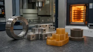
13. Material Selection
Machined parts can be made from various materials, including metals and plastics.
Extremely hard materials are difficult to machine and may cause increased tool vibration (resulting in lower quality). Extremely soft materials and those with very low melting points may deform when in contact with cutting tools. Below are the most common materials for machined parts:
Metals: Aluminum alloys, steel, stainless steel, magnesium, titanium, zinc, brass, bronze, copper.
Plastics: ABS, PC, ABS+PC, PP, PS, POM, PMMA (acrylic), PAGF30, PCGF30, PTFE, DHPE, HDPE, PPS, PEEK. (Less common: PA GF50, PPS GF50.)
CNC Milling DFM Risk and Buyer Decision Table
CNC Milling DFM Risk and Buyer Decision Table
| Design feature | Manufacturing risk | Buyer decision before RFQ |
|---|---|---|
| Deep, narrow pocket | Long tool reach, vibration, chip evacuation, and limited holder clearance | Confirm the functional depth; widen the opening or increase internal radii where the design permits |
| Thin wall or floor | Deflection during cutting and movement after unclamping | Define the functional wall, datum condition, and how the part should be inspected |
| Features on multiple faces | Additional setups and accumulated relationship error | Identify which features must relate to one datum system or be machined in the same setup |
| Small or deep hole | Tool breakage, poor chip removal, burr access, and difficult verification | State whether diameter, depth, bottom form, and full-depth tolerance are functionally required |
| Tight internal corner | Small cutters, slower paths, or an inaccessible sharp corner | Allow a practical radius or relief unless the mating geometry requires another process |
| Thread near a shoulder or blind-hole bottom | Insufficient tool runout, incomplete thread, or trapped chips | Specify thread system, class, engagement length, relief, and gauge requirement |
| Coated or cosmetic interface | Finish buildup, mask lines, handling marks, or changed fit | Mark masked zones, cosmetic faces, and whether dimensions apply before or after finishing |
Summary
In summary, this post outlines essential factors to optimize CNC milling designs. It emphasizes minimizing setup and machining times, enhancing precision, and addressing challenges like narrow cavities, thread depths, tool retraction, surface complexities, and material selection for efficient and high-quality outcomes.
Frequently Asked Questions
Frequently Asked Questions
What information should I send for a CNC milling DFM review?
Send a 3D CAD model and controlled 2D drawing with matching revision, material, quantity, tolerances, datums, threads, surface requirements, finish, inspection documents, and packaging needs.
Do deep pockets always require a design change?
No. The risk depends on depth, opening width, internal radii, material, tool and holder access, required surface, and tolerance. Ask the supplier to review the actual geometry before changing a functional feature.
How should I specify internal corner radii?
Use the largest radius the mating design allows and identify any corner that must remain sharp or needs relief. The supplier can then review cutter access and propose a practical route.
Can CNC milling produce thin walls?
Thin walls may be possible, but material, wall height, surrounding stock, clamping, tool access, finish, and inspection condition affect distortion risk. Confirm the design from the project drawing rather than relying on one universal minimum.
How can I reduce setup-related risk?
Define functional datums and identify features that must remain closely related. Where practical, those features can be planned in a common setup; otherwise the quotation should explain transfer and inspection.
Should dimensions apply before or after surface finishing?
State this explicitly for every fit, sealing face, thread, bore, shaft, or cosmetic interface affected by the finish. Also mark masked zones and any permitted coating allowance.
When the RFQ package is ready, request a CNC machining quote.