


5-Axis CNC Machining Services for Complex Custom Parts
A part does not need five-axis machining simply because it looks complex, and a “5-axis” quote does not automatically mean all five axes move at once. The buying decision depends on feature direction, tool access, setup relationships, surface continuity, workholding, and inspection. CNCMAVEN reviews custom metal and plastic parts to determine whether 3+2 positioning, continuous five-axis motion, conventional milling, or a combined route best fits the drawing. Send the model, controlled drawing, material, quantity, finish, and inspection scope for project-specific review.

Process fit
Select the route from part geometry and function.
Quality planning
Connect critical features to an inspection plan.
Project review
Review drawings and requirements before quotation.
When does a part genuinely need 5-axis machining?
Five-axis machining is useful when tilting or rotating the part or tool provides access that would otherwise require several fixtures, long tools, or impractical setups. The strongest candidates have features on multiple faces, compound angles, deep areas obstructed from a vertical approach, or contoured surfaces that need controlled tool orientation.
- Ports, holes, or sealing faces directed along several non-parallel vectors
- Multi-sided housings, brackets, manifolds, and structural components
- Impeller-like, blade-like, or sculpted surfaces requiring changing tool orientation
- Deep cavities where a shorter tilted tool can improve access and stability
- Features whose positional relationship is difficult to preserve across repeated manual setups
- Parts needing machining close to an undercut or obstructed region, subject to tool and holder clearance
Five-axis machining is not a substitute for a complete datum scheme or practical geometry. A simple plate, open pocket, or part with accessible orthogonal faces may be more economical on a conventional route. For the wider process range, see CNCMAVEN’s custom CNC machining services.
3+2 positioning and continuous 5-axis are different purchases
Buyers should ask which five-axis strategy the quotation assumes. In 3+2 machining, the rotary axes position the part or tool at an angle and remain fixed while the cutting axes move. In continuous five-axis machining, rotary and linear axes can move together during the cut. Both approaches can be appropriate, but they solve different geometry and surface problems.
| Decision point | 3+2 positional machining | Continuous 5-axis machining |
|---|---|---|
| Typical need | Multiple angled faces, holes, pockets, or planes that can each be cut from a fixed orientation | Contoured surfaces or geometry requiring tool orientation to change along the toolpath |
| Axis behavior during cutting | Rotary axes index to an orientation and are normally held while a feature is machined | Linear and rotary axes may move together as the surface is cut |
| Programming and verification | Requires indexed setup planning and clearance checks for each orientation | Requires detailed toolpath, machine-kinematic, holder, fixture, and collision verification |
| Surface implication | Well suited to discrete planar or angled features; transitions between indexed regions must be reviewed | May better maintain tool orientation across a freeform surface, subject to toolpath and machine behavior |
| Buyer question | Can critical features be completed in one clamping, and which axes are indexed? | Which surfaces require simultaneous motion, and how will toolpath and inspection be validated? |
Do not specify continuous five-axis motion as a prestige requirement. Specify the geometry, datum relationships, surface criteria, and access constraints; then ask the supplier to explain the proposed route. The result may be 3+2, continuous motion for selected surfaces, or a combination.
Complex surfaces and multi-face features create different risks
Freeform surfaces are mainly a tool-orientation and surface-continuity problem, while multi-face prismatic parts are mainly an access and datum-relationship problem. Combining both in one drawing requires clear separation of functional surfaces, cosmetic surfaces, and interfaces that drive assembly.
| Geometry type | Main manufacturing concern | Information the buyer should define |
|---|---|---|
| Freeform or blade-like surface | Tool orientation, step-over pattern, surface blending, and holder clearance | Surface profile control, texture or appearance requirement, edge transitions, and functional zones |
| Angled bore or port | Approach direction, tool reach, breakout, burr access, and positional relationship | Datum reference, true position or angular requirement, depth, bottom form, and deburring criteria |
| Multi-face housing | Maintaining relationships between mounting, sealing, and locating faces | Primary datum structure, critical interfaces, flatness or orientation needs, and inspection access |
| Deep cavity | Tool and holder interference, chip evacuation, reach, and vibration | Minimum necessary depth, internal radii, wall thickness, floor condition, and inaccessible zones |
| Thin curved wall | Deflection, residual stress, stock-removal balance, and measurement condition | Wall profile, datum restraint, free-state or restrained inspection, and permitted local variation |
A smooth rendering is not an acceptance specification. Use the 2D drawing to state which modeled surfaces carry profile tolerances, where blending marks are unacceptable, and how edges should transition. If a digital model is the authority for a surface, identify its revision and the drawing note that controls interpretation.
Datum strategy matters more than reducing setup count
One-clamping machining can reduce some repositioning error, but it does not guarantee that every feature meets function. The program, fixture, stock, machine coordinate system, and inspection must all interpret the same functional datums. A five-axis process built around convenient manufacturing datums may still miss the assembly relationship if the drawing is ambiguous.
- Choose datums from stable functional surfaces rather than inaccessible theoretical points.
- Define which mounting face establishes orientation and which features locate the part.
- Use geometric controls to relate angled holes, ports, sealing faces, and profiles to the datum reference frame.
- State whether profile requirements apply to the complete surface, selected zones, or a boundary transition.
- Identify post-finish dimensions and whether coating or treatment changes controlled interfaces.
- Provide mating-part context where it clarifies the intended fit or seal.
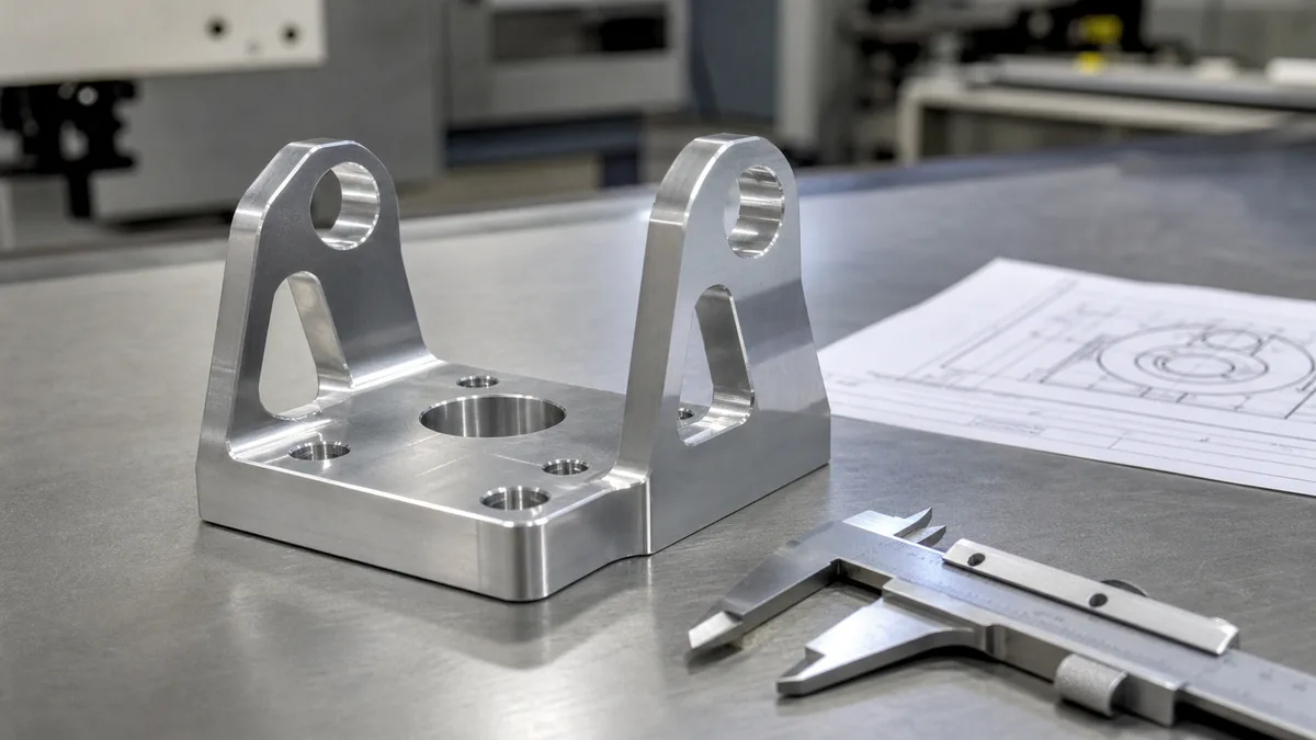
Tolerance and inspection must be planned together
Achievable tolerance depends on the specific material, part size, feature direction, wall thickness, cutter reach, rotary orientation, setup sequence, finish, and measurement method. CNCMAVEN therefore reviews tolerances from the drawing rather than promising one fixed value for all five-axis parts.
Inspection becomes more demanding when features point in multiple directions or surfaces are defined by 3D profiles. Conventional gauges may suit threads and simple bores, while multi-directional positions or surface profiles may require a coordinate-based measurement strategy or dedicated fixtures. The chosen method must be agreed for the project; this page does not imply a particular machine or metrology inventory.
- Drawing review: confirm revision, datum reference frame, critical characteristics, material, finish, and documentation scope.
- Manufacturing-to-inspection alignment: decide how the setup coordinate system and inspection datum establishment correspond.
- First-part verification: check access-sensitive, setup-sensitive, and functional relationships before the full quantity proceeds.
- In-process control: monitor features that can drift through tool wear, heat, or changing stock conditions as appropriate.
- Final acceptance: inspect the agreed characteristics with suitable calibrated methods and issue only the records included in the order.
If a full dimensional report, surface comparison, first-article template, sampling plan, or customer-specific form is required, include it at RFQ stage. Inspection access and data format can affect the proposed route.
DFM for five-axis parts should start with access
A practical DFM review asks whether the cutter and holder can reach the feature safely from an available orientation. It also checks whether stock and fixture clearance remain adequate as the rotary axes reposition. Proposed changes should be approved by the buyer; the released drawing remains controlling.
- Hidden regions: rotating the part does not make every undercut accessible. Identify reverse-facing geometry and accept a secondary process where required.
- Deep narrow cavities: enlarge openings, increase internal radii, or reduce depth when function permits to improve tool and holder clearance.
- Tight concave curvature: may force a small tool and longer machining time. Separate functional curvature from cosmetic styling.
- Thin floors and walls: may move as surrounding stock is removed. Review stock sequence, wall transitions, and inspection restraint.
- Tool-tip-only contact: can produce poor cutting conditions on steep surfaces. Allow tool orientation and surface strategy to be optimized.
- Intersecting holes and ports: define breakout condition, internal burr acceptance, and cleaning access.
- Sharp internal corners: require a practical radius or relief because rotating cutters have finite geometry.
- Fixture obstruction: preserve surfaces or stock that can locate and hold the part without blocking critical access.
Review Your 5-Axis Part
Send the current drawing and project requirements for review.
Materials, finishing, and edge requirements
The existing CNCMAVEN CNC service range includes aluminum, stainless steel, copper and brass, and engineering plastics. Exact grade and condition must be confirmed for each quotation because material affects cutting behavior, toolpath planning, distortion, deburring, and surface response.
Finishing must be considered before machining is released. Identify cosmetic zones, masked surfaces, thread protection, coating allowance, surface-treatment prerequisites, and whether controlled dimensions apply before or after finishing. CNCMAVEN’s surface finishing options page outlines related processes, subject to project confirmation.
What should be in a 5-axis machining RFQ?
A complete RFQ lets suppliers compare routes instead of guessing what “five-axis quality” means. Send the same controlled package to each supplier and ask them to state whether the quote assumes 3+2, continuous motion, conventional machining, or a combination.
- Native or neutral 3D CAD model and a dimensioned 2D PDF drawing
- Matching part number and revision, including the authority for modeled surfaces
- Exact material grade and condition, plus any approved substitution process
- Prototype, order, and expected repeat quantities
- Functional datums, geometric controls, critical interfaces, and mating context
- Surface-profile, texture, blend, edge, burr, and cosmetic requirements
- Finish, masked zones, and pre-finish versus post-finish dimensional intent
- Inspection method or report scope where contractually required
- Packaging needs and delivery destination
To start a technical review, request a 5-axis CNC machining quote and attach the current revision. For a general comparison of process categories, read 3-axis, 4-axis, and 5-axis CNC machining.
Frequently asked questions
In 3+2 machining, rotary axes position the part or tool and are normally held while cutting occurs from that orientation. Continuous five-axis machining can move rotary and linear axes together during the cut, which may be needed for selected contoured surfaces.
No. Many multi-face parts can be produced with 3+2 positioning or a combination of indexed and conventional operations. The drawing, tool access, surface continuity, datum relationships, and cost should determine the route.
Send a 3D CAD model and controlled 2D drawing with matching revision, material, quantities, datums, geometric tolerances, surface requirements, finish, inspection scope, packaging, and delivery destination.
Tolerance is confirmed from the specific drawing. Material, geometry, wall thickness, tool reach, rotary orientation, setup sequence, finish, and inspection method all affect what can be achieved and verified.
The method depends on the surface definition, tolerance, datum system, access, and required report. Agree on the inspection strategy and data format before production rather than assuming one method suits every freeform surface.
Some obstructed regions become accessible when the tool or part is reoriented, but five-axis motion does not make every undercut machinable. Reverse-facing geometry, holder interference, and tool shape may still require design changes or another process.
Request a 5-Axis Machining Review
Send the current drawing and project requirements for review.