


CNC Prototyping Services
A useful CNC prototype should answer manufacturing questions before production tooling or a larger order is approved. The part must be close enough to the intended design to test fit, assembly, function, finish, and inspection requirements. That starts with a complete RFQ: a 3D model, dimensioned drawing, material and finish specifications, quantity, target date, and the features that matter most. CNCMAVEN reviews these inputs for prototype machining and provides feedback where geometry, tolerance, stock choice, or finishing may affect the build.
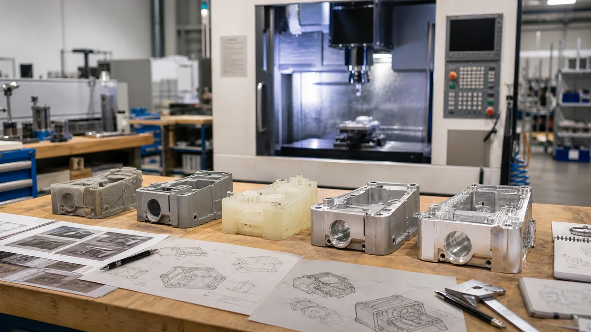
Process fit
Select the route from part geometry and function.
Quality planning
Connect critical features to an inspection plan.
Project review
Review drawings and requirements before quotation.
When CNC machining is the right prototyping process
CNC machining suits prototypes that must be made from engineering-grade metal or plastic and represent the final part closely. It avoids dedicated molding tools, supports one-off parts and small batches, and lets revisions be incorporated through model and program changes. Typical candidates include housings, brackets, fixtures, heat-management parts, shafts, manifolds, and mechanical assemblies that need functional testing.
It is less attractive when a design can only be produced economically with casting, molding, or another near-net-shape method, or when organic internal geometry cannot be reached by cutting tools. Additive manufacturing may suit those early shapes better. A project may use a visual printed model for form, followed by a machined part for load, fit, thermal, sealing, or thread tests. For available milling, turning, and related capabilities, see our CNC machining services.
Choose the prototype route by what you need to learn
The right process follows the test objective, not simply the file format. Tell the supplier which decision the prototype must support so time and inspection effort are focused on the features that carry real risk.
| Objective | Typical approach | What to specify |
|---|---|---|
| Form and assembly fit | Machined plastic or aluminum with general tolerances on noncritical dimensions | Mating faces, keep-out zones, fasteners, and assembly sequence |
| Functional or load test | Material chosen to represent the intended part as closely as practical | Load direction, critical radii, threads, inserts, and sensitive features |
| Thermal or electrical test | Metal part with representative contact surfaces and finish | Flatness-critical interfaces, conductivity needs, coatings, and masking |
| Seal or fluid test | Controlled bores, grooves, ports, and sealing faces | Seal type, surface requirements, pressure conditions, and test method |
| Appearance review | Machined part with the intended cosmetic finish where feasible | Color reference, texture, gloss, visible faces, and witness marks |
Material selection for CNC prototypes
Prototype material should match the question being tested. The final production alloy is useful for structural, thermal, corrosion, wear, thread, or finishing evaluation, but may be unnecessary for a simple fit check. A readily available substitute can simplify sourcing, yet it must be documented because stiffness, strength, hardness, temperature response, chemical resistance, and coating behavior may change the result.
Aluminum is often considered for lightweight housings, brackets, heat sinks, and general mechanical prototypes because many grades machine efficiently and accept common finishes. Stainless steel is considered when corrosion resistance, strength, wear, or a production-representative appearance matters, although machining strategy and cost differ by grade. Mild and alloy steels suit fixtures, shafts, tooling components, and load-bearing parts. Brass and copper alloys may suit electrical, thermal, fluid, or wear-related tests, subject to the exact grade.
Engineering plastics can reduce weight and avoid electrical conductivity. POM is often considered for stable mechanical parts; nylon for wear and toughness; PC or acrylic for transparent or impact-related evaluation; and high-performance polymers when temperature or chemical exposure justifies their cost. Moisture response, internal stress, wall thickness, and workholding matter. Specify the exact resin or accepted equivalent instead of writing only “plastic.”
Prototype DFM: decisions to make before programming
DFM review should separate design intent from dimensions inherited from the CAD model. A machinist needs to know which features control function and which can change without invalidating the test. That distinction can prevent unnecessary setups, special tools, slow finishing passes, and inspection work.
- Mark critical dimensions. Identify datums, fits, sealing faces, bearing seats, hole positions, and assembly interfaces.
- Use realistic internal corners. Milling tools leave radii in pockets; larger radii usually permit stronger tools.
- Review deep pockets and narrow slots. Tool reach, deflection, chip evacuation, and visibility affect machining and inspection.
- Control thin walls deliberately. Thin sections may move during clamping or cutting; state their functional reason and measurement condition.
- Avoid blanket tight tolerances. Apply tighter limits only where fit, sealing, motion, alignment, or performance requires them.
- Make threads unambiguous. State standard, size, pitch, thread depth, and whether inserts are required.
- Plan finishing and masking. Coating thickness can change fits, threads, holes, and electrical contact areas.
- Allow practical workholding. Provide stable clamping surfaces and identify cosmetic faces that cannot accept witness marks.
If a feature cannot be verified with normal measuring equipment, agree on the inspection method before machining. A sound DFM change preserves the test objective while reducing avoidable manufacturing risk.
Review Your Prototype Requirements
Send the current drawing and project requirements for review.
From RFQ to machined prototype
A controlled order begins with file and revision review. The supplier checks that model and drawing agree, confirms units, quantity, material, finish, and destination, then raises questions about missing or conflicting requirements. After DFM points are resolved, planning determines whether the part needs milling, turning, multiple orientations, special workholding, or outside finishing.
Programming and setup follow the approved revision. Important features are checked during machining where practical. Parts are deburred and cleaned, followed by specified finishing. Final inspection records should match the agreed scope rather than an assumed “full inspection” whose meaning varies. Give every model and drawing a clear revision, withdraw obsolete files, and document approved deviations.
Quality planning for prototype parts
Prototype quality does not always mean measuring every CAD dimension. The inspection plan should match the build purpose and the risk of a wrong result. A fit-check component may need a focused report; a sealing, motion, or validation part may need more evidence and defined test conditions.
| Quality item | Buyer decision | Useful RFQ detail |
|---|---|---|
| Drawing and revision | Which document controls acceptance? | Revision, units, projection, and precedence rule |
| Critical dimensions | Which measurements affect the test? | Numbered characteristics, datums, fits, and tolerance basis |
| Material verification | What traceability is required? | Exact grade and requested supplier documentation |
| Surface and edges | What is functional or cosmetic? | Roughness where needed, deburr expectations, and visible faces |
| Inspection record | What evidence must ship? | Focused report, sampling expectation, or agreed full report |
| Special tests | Who performs them and how? | Leak, fit, coating, hardness, or assembly-test procedure |
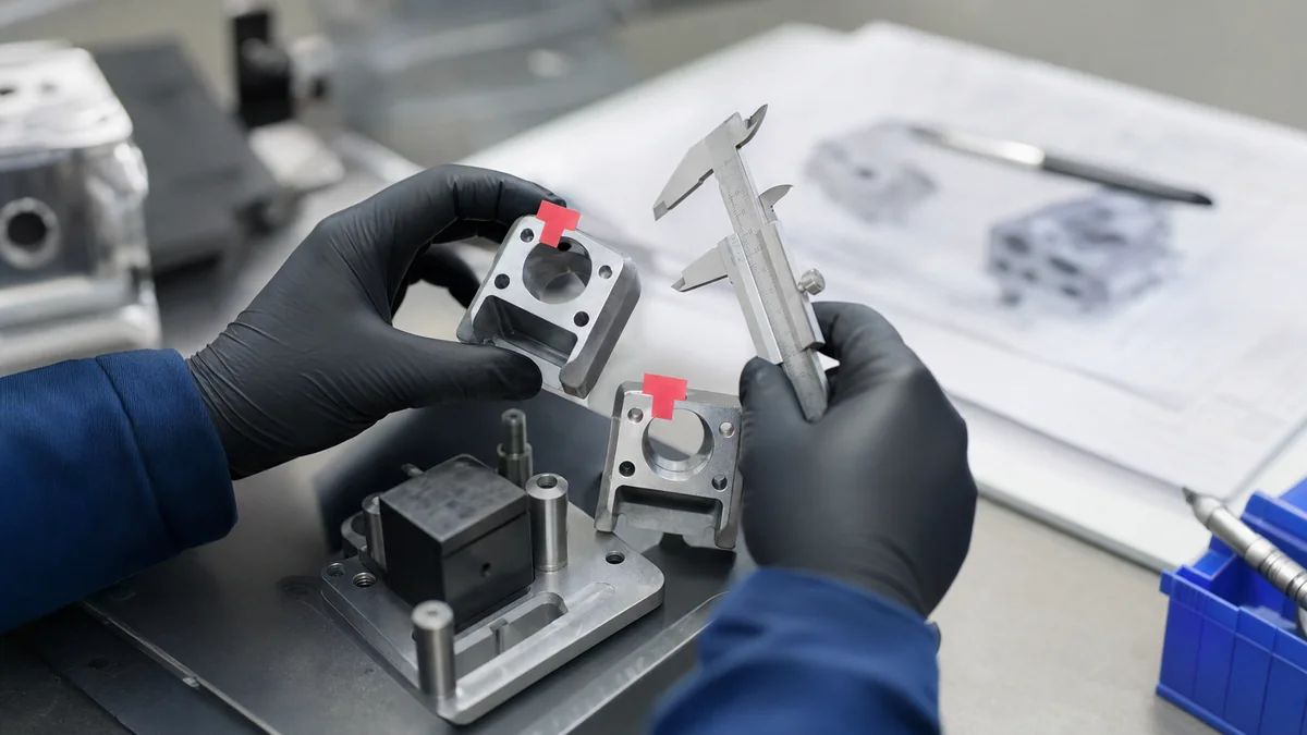
Measurement conditions matter for flexible plastics, thin walls, large spans, and temperature-sensitive fits. Agree whether dimensions are checked free-state or restrained, and identify fixtures or mating components used for acceptance.
Applications for machined prototypes
Machined prototypes are used when teams need evidence from real geometry and material. Examples include automation brackets, sensor housings, optical mounts, electronics enclosures, vehicle components, laboratory fixtures, pumps, valves, and industrial replacement parts. An enclosure may prioritize connector alignment, heat transfer, shielding contact, and cosmetics. A motion component may prioritize bearing fits and coaxial features. A fluid component may prioritize sealing geometry, threads, cleanliness, and an agreed pressure test. Explain the operating context so DFM and quality questions focus on features that could invalidate the test.
How to compare CNC prototyping quotations
Compare quotations on scope before price. A lower number may exclude finishing, material documentation, dimensional reporting, packaging, or shipping. It may also reflect different tolerance assumptions or an unapproved material substitute.
- Confirm that each quote references the same model and drawing revision.
- Check material grade and condition, and require approval for substitutes.
- Compare quantity, setup allocation, and any proposed partial deliveries.
- Verify finish, color, texture, masking, and cosmetic criteria.
- Ask which dimensions and documents are included in inspection.
- Separate manufacturing time from transport time and allow for drawing questions.
- Clarify nonconforming parts, approved deviations, and design changes after order.
- Review payment, shipping terms, import responsibilities, and protective packaging.
A capable response identifies uncertainties rather than quietly pricing around them. The useful quotation gives engineering and procurement a shared understanding of what will be made, checked, documented, and delivered.
What to include in your prototype RFQ
Send native or neutral 3D CAD, a PDF drawing for tolerances and notes, revision identifiers, quantities, material, finish, destination, and requested timing. Add an annotated image if cosmetic faces or assembly orientation are difficult to communicate. State the prototype purpose, dimensions that affect the decision, acceptable material alternatives, documentation, and whether mating parts are available.
For repeated builds, note whether the order is a one-time experiment or the start of a bridge-to-production program. This does not guarantee production pricing, but it helps avoid choices that make later scaling unnecessarily difficult.
Request a CNC prototyping review
Send your model, drawing, quantity, material, finish, and inspection expectations for review. CNCMAVEN can assess the machining route and return questions or DFM observations based on the supplied requirements. Use the Contact Us page to start an RFQ. Call out any mandatory tolerance, finish, documentation item, or test method so it can be confirmed before the order proceeds.
Frequently asked questions
Send a 3D CAD file plus a dimensioned PDF drawing. Identify units, revision, material, finish, tolerances, datums, threads, and critical features. Include quantity, destination, timing, and required inspection records.
Use it when the test depends on strength, stiffness, wear, heat transfer, corrosion, threads, or finishing behavior. A documented substitute may suit form and fit checks, but its limitations should be understood.
Apply tight tolerances only to features that control fit, sealing, motion, alignment, or performance. Achievable results must be reviewed against material, geometry, feature size, setup, and inspection method.
Many prototypes can receive representative finishes, subject to material and supplier capability. Specify visible faces, color or texture reference, masking, coating-sensitive fits, and acceptance criteria.
Request evidence that matches the risk: a focused critical-dimension report, material documentation when needed, and agreed finish or functional test records. Define “full inspection” precisely if required.
Keep test-critical features, then relax noncritical tolerances, enlarge internal radii, reduce deep narrow pockets, simplify setups, accept standard stock sizes, and limit cosmetic finishing to required surfaces.
Request a CNC Prototyping Review
Send the current drawing and project requirements for review.