Type II anodizing is usually specified to protect and color aluminum CNC parts, but the finish can still cause rejects when the drawing does not say what matters. A quote can be accurate only when the shop knows the required finish, color, thickness range, cosmetic surfaces, masked areas, and which dimensions apply after finishing. This guide turns those decisions into practical drawing and RFQ notes.
Start with the function of the finish
Type II anodizing is a sulfuric-acid anodic coating commonly selected when an aluminum part needs corrosion resistance, a dyed appearance, electrical insulation at the surface, or a more uniform presentation than bare machining marks. It is not a substitute for a wear coating where sliding contact, abrasive dust, or repeated bearing movement dominates. In those cases, compare hard anodizing, plating, a stainless material, or a design change rather than assuming a thicker Type II film will solve the wear problem.
State the part’s functional priority before choosing a color. A front panel may prioritize appearance; an internal bracket may prioritize corrosion protection; a heat-sensitive housing may prioritize a controlled contact surface. That priority changes which faces need cosmetic control, which areas can accept rack marks, and whether masking is more important than color matching.
| Requirement | Put it on the drawing or RFQ | Why it changes the process |
|---|---|---|
| Finish type | Type II anodize and the governing customer or industry specification | Prevents substitution with a different anodic process. |
| Color and appearance | Clear/natural or named color; identify cosmetic faces and approved sample if color match is critical | Alloy, texture, lot, and lighting can affect visual appearance. |
| Thickness | Specify the required range and the reference standard when applicable | Thickness affects protection, fit, and inspection method. |
| Critical dimensions | Mark as final-finish dimensions and identify datums | The machinist must plan stock allowance and measurement timing. |
| Masking | Identify threads, grounding pads, sealing lands, bores, or contact zones | Masking changes racking, handling, and cost. |
Do not estimate fit changes with a universal rule
Anodizing changes the surface, but the final dimension is not governed by one universal “half in, half out” allowance. Pretreatment can remove material; oxide grows inward and outward; alloy, geometry, coating target, and process control all matter. A generic allowance copied from another part can leave a threaded hole tight or a bore outside tolerance.
For a critical bore, mating diameter, thread, or seal land, specify whether the dimension applies before or after anodizing. Then ask the finishing supplier how the proposed process will be controlled and measured for that feature. A practical route is to define a finished-size requirement and agree the inspection method before machining begins. If the fit is sensitive, order a representative coupon or first article before releasing a large lot.
Threads, contact pads, and sealing faces need explicit calls
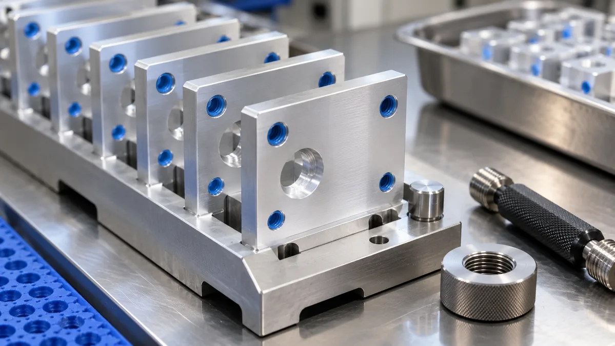
Threads are a common source of avoidable rework. Do not rely on a note such as “anodize all over” when threaded holes must accept a screw after finishing. Identify threads that require masking, post-process chasing, or a validated finished gage. The same approach applies to grounding pads, RF contact faces, press fits, precision bores, and gasket sealing lands. If a masked zone is acceptable only on one non-cosmetic face, show the permitted rack or mask location instead of leaving the choice to the finishing line.
Consider the assembly sequence as well. A part that will later be bonded, electrically grounded, or welded may need bare metal at a designated location. A part with laser-marking, adhesive, or conductive coating after anodizing needs compatible instructions. These are small drawing notes, but they prevent a finished part from arriving with a functionally wrong surface.
Choose cosmetic requirements realistically
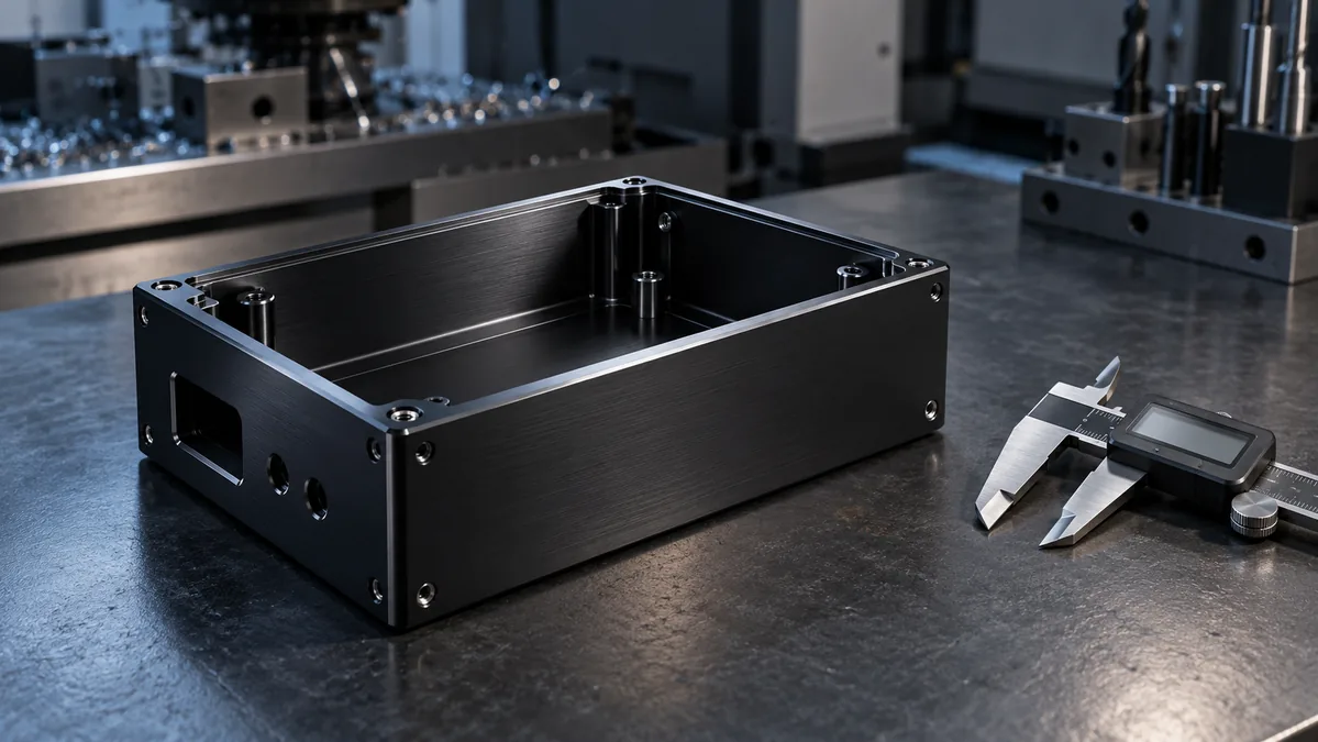
Black and dyed Type II anodize can look different across alloy grades, material lots, surface textures, part thicknesses, and viewing conditions. A part machined from mixed material conditions or with bead-blasted and as-machined faces will not necessarily present as one uniform shade. If appearance is a release criterion, define the visible faces, target texture, acceptable variation, and the approval route for a sample or color standard. Avoid calling a color “exact” without a measurable acceptance reference.
For non-cosmetic hardware, do not pay for color matching that does not affect function. A clear or natural finish, a limited cosmetic zone, and an allowed rack-mark location can reduce unnecessary sorting and delay. See our surface-finish selection guide when finish decisions need to be compared against corrosion, appearance, and downstream assembly requirements.
Use this drawing and RFQ checklist
- Current drawing revision and 3D model, with cosmetic faces clearly identified.
- Aluminum grade, temper, and material-certificate requirement where applicable.
- Type II anodize requirement, governing specification or customer standard, color, and seal requirement if relevant.
- Coating thickness range and whether critical dimensions are before- or after-finish.
- Masked features: threads, bores, contact pads, grounding locations, seal lands, and rack-mark zones.
- Surface preparation before anodizing: as-machined, bead-blasted, brushed, or another defined texture.
- Inspection request: final dimensional report, thread gaging, visual standard, or first-article sample.
- Packaging instructions that keep cosmetic surfaces from rubbing during shipment.
Inspect what the drawing actually requires
Inspection should map to the release risks, not just to a generic appearance check. Verify that the finish is present on required faces, masked zones remain functional, critical finished dimensions are measured with the agreed method, and the color or texture meets the approved acceptance route. For first articles, include the part revision, material identity, finish callout, measurement results, and any permitted deviations in one review package. That gives purchasing and engineering the same evidence before production quantities are released.
If the part has both a tight mechanical interface and a cosmetic requirement, resolve the interface first. A good-looking surface does not compensate for a screw that will not assemble or a sealing face that no longer closes. For broader finish tradeoffs, link the drawing note to the part function rather than treating anodizing as a decorative afterthought.
Final decision: write the callout before the quote
A usable Type II anodizing specification tells the supplier what to finish, what to protect, what dimensions control after finishing, and how to judge the result. The most effective RFQs separate cosmetic surfaces from functional interfaces and identify any critical inspection evidence up front. That reduces back-and-forth before machining and makes the finished part easier to accept when it arrives.