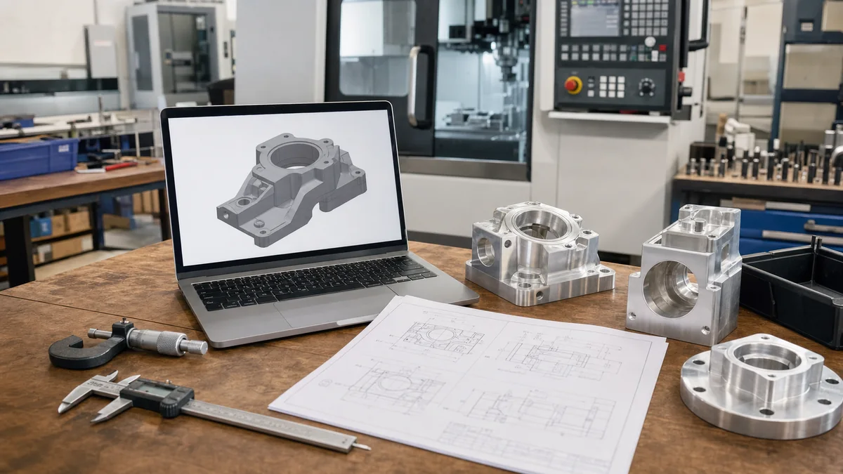
A CAD file can make a CNC machining quote faster, but only if it gives the supplier enough information to understand the part, the manufacturing route, and the acceptance criteria. A 3D model shows geometry. It does not always show tolerances, threads, material condition, surface finish, cosmetic requirements, or how the part will be inspected.
This guide explains which files to send, when a drawing is still necessary, and how to avoid the clarification loops that slow CNC quotes.
Start with the file that controls geometry
For most CNC machined parts, a STEP file is the safest neutral 3D format to send because it preserves solid geometry better than mesh formats. Native CAD files can be useful when the supplier supports the same software, but neutral files reduce compatibility problems. IGES may still appear in older workflows, though it can create surface-repair work. STL is useful for 3D printing, but it is usually a poor master file for CNC machining because it describes a faceted mesh rather than exact machinable surfaces.
| File type | Good use | Risk if used alone |
|---|---|---|
| STEP / STP | Primary solid model for most CNC RFQs and CAM review. | Still needs a drawing when tolerances, threads, finish, or inspection rules matter. |
| Native CAD | Useful for design intent, assemblies, and editable feature history when compatible. | Supplier may not have the same CAD version or may export its own neutral file. |
| IGES | Legacy surface exchange for some workflows. | Can require surface repair before programming. |
| STL | Good for visual reference or additive manufacturing. | Not ideal for CNC because mesh facets do not define precise analytic geometry. |
| PDF drawing | Controls tolerance, material, finish, thread, and inspection notes. | Cannot replace a usable 3D model for complex geometry. |
Use the drawing to control what the model cannot say
A CNC supplier can often quote a simple prototype from a model only, but that does not mean the model-only route is best. Drawings are still important when the part includes threaded holes, press fits, dowel locations, sealing faces, bearing bores, cosmetic surfaces, heat treatment, coating thickness, or required inspection reports. The drawing tells the shop which dimensions are critical and which are general.
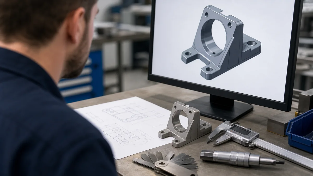
If every dimension is marked as tight, the supplier has to price extra inspection and slower machining. If no dimensions are marked as critical, the supplier must guess what controls fit. A useful drawing separates functional dimensions from general geometry and makes the datum scheme clear enough for inspection.
What a complete CNC RFQ package should include
- 3D CAD file, preferably STEP, exported from the controlled revision.
- PDF drawing with material, finish, tolerance block, revision, and thread notes.
- Quantity, batch schedule, and whether the order is prototype, bridge production, or production.
- Critical-to-function features, mating parts, or assembly context.
- Required reports such as material certificate, dimensional report, CMM report, or first article inspection.
- Surface finish expectations, deburring rules, visible faces, and packaging needs.
For part geometry review, CNCMAVEN’s CNC machining services team can check manufacturability before production. The DFM considerations for CNC milling guide is also useful when the model has deep pockets, thin walls, or tight internal corners.
Common file problems that slow quoting
The most common RFQ problem is mismatch. The model says one revision, the drawing says another, and the email mentions a third change. Another common problem is missing thread detail. A model may show a hole, but the drawing must state thread standard, size, depth, class, and whether it is blind or through. Surface finish can also create confusion when a buyer writes “smooth finish” instead of defining machining marks, roughness, bead blasting, anodizing, or cosmetic faces.
| Problem | What the supplier has to ask | Better instruction |
|---|---|---|
| Model and drawing do not match | Which revision controls the quote? | Use one revision number and export files from the same released design. |
| Thread shown only as a hole | What thread size, depth, and tolerance are required? | Call out the thread standard, depth, and insert requirement on the drawing. |
| All dimensions are tight | Which features actually control function? | Use general tolerances and mark only critical features tightly. |
| Finish is vague | Is the surface cosmetic, functional, coated, or simply deburred? | Define visible faces, roughness where needed, and finish process. |
| No assembly context | Which faces locate against the mating part? | Send mating interface dimensions or an assembly screenshot without proprietary detail. |
How to prepare CAD files before sending them
Before sending an RFQ, open the exported STEP file in a viewer and confirm that geometry, units, and orientation are correct. Remove unrelated bodies, old design options, and hidden construction parts. If the supplier only needs one component, do not send an entire assembly unless the assembly explains mating conditions. For proprietary products, suppress nonessential surrounding components and include only the interface geometry needed to understand fit.
Compress the RFQ package into a simple folder with clear filenames. Use names such as part-number-revision-step and part-number-revision-drawing instead of final-final-new. That small discipline reduces the risk of quoting from an obsolete model.
When to ask for DFM feedback
Ask for DFM feedback before locking the design if the part has deep cavities, thin walls, tight flatness, multiple setups, complex 5-axis features, hard material, or expensive finishing. A supplier can often suggest a larger corner radius, alternate datum, standard stock thickness, or relaxed noncritical tolerance that saves machining time without changing the product function.
FAQ
Is a STEP file enough for CNC machining?
A STEP file is often enough for simple model-based prototypes, but a drawing is still needed when tolerances, threads, material, finish, inspection, or cosmetic requirements matter.
Should I send STL files for CNC machining?
STL files are usually not ideal for CNC machining because they are mesh files. Send STEP or a native CAD file when possible, and use STL only as a reference if needed.
What should be on a CNC machining drawing?
At minimum, include material, revision, tolerance block, critical dimensions, threads, surface finish, deburring notes, and any required inspection or certification.